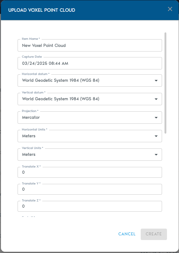
| **Field** | **Description** |
| **Item Name** | A descriptive, readable name for the new point cloud entity. |
| **Capture Date** | *(Optional)* The original date the point cloud data was collected. |
| **Horizontal Datum** | The horizontal reference system used (e.g., WGS 84, NAD83). |
| **Vertical Datum** | The vertical reference system used for elevation or depth. |
| **Projection** | The coordinate projection applied to the dataset. |
| **Horizontal Units** | Units used for horizontal measurements (e.g., meters or feet). |
| **Vertical Units** | Units used for vertical measurements (e.g., meters or feet). |
| **Field** | **Description** |
| **Item Name** | A readable, descriptive name for the new imagery set. |
| **Capture Date** | *(Optional)* The original date when the imagery was captured. |
| **Horizontal Datum** | The horizontal datum used in the world registration files (e.g., WGS 84, NAD83). |
| **Projection** | The projection used by the world registration files. |
| **Horizontal Units** | Units used in the registration files (typically meters or feet). |
| **Image Format** | **Expected World File Extension** |
| .JPG | .JGW |
| .PNG | .PGW |
| .BMP | .BPW |
| .TGA | .TAW |
| .TIF | .TFW |
| Item Name | A readable name for the new entity |
| Minimum Height | Elevation value for black pixels in the heightmap |
| Maximum Height | Elevation value for white pixels in the heightmap |
| Capture Device | An optional string to identify capture device |
| Capture Date | An optional field containing the original capture date |
| Horizontal Datum | The horizontal datum used in the heightmap |
| Vertical Datum | The vertical datum used in the heightmap |
| Projection | The projection used by the heightmap |
| Horizontal Units | The horizontal unit type used in the heightmap |
| Vertical Units | The vertical unit type used in the heightmap |
| Image Format Extension | Expected World File Extension |
| .PNG (16bit grayscale) | .PGW |
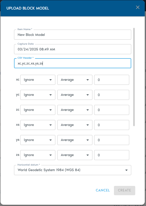
| **Field** | **Description** |
| **Item Name** | A descriptive name for the new block model entity. |
| **Capture Date** | *(Optional)* The original date the model data was captured. |
| **CSV Header** | A comma-separated line of headers that define how each column in the block model should be interpreted. (Details below.) |
| **Horizontal Datum** | The horizontal reference system used in the model. |
| **Vertical Datum** | The vertical reference system used for elevation values. |
| **Projection** | The map projection used in the dataset. |
| **Horizontal Units** | Units for X and Y coordinates (e.g., meters, feet). |
| **Vertical Units** | Units for Z coordinates (e.g., meters, feet). |
| [](https://help.mystart.com/uploads/images/gallery/2025-03/WvSimage.png) | [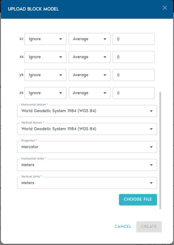](https://help.mystart.com/uploads/images/gallery/2025-03/fkFimage.png) |
| **Type** | **Purpose** |
| **Ignore** | Exclude this column from processing. |
| **Set** | The column contains a small set of repeating categorical values. |
| **Value** | Numeric values (e.g., grades, densities). |
| **Block Centroid X/Y/Z** | Coordinates for the block’s center point. |
| **Block Origin X/Y/Z** | Coordinates for the block’s origin corner. |
| **Block Dimension X/Y/Z** | Size of the block along each axis. |
| **LOD Option** | **Description** |
| **Average** | Average of all higher-resolution values. |
| **Min** | Minimum value from the finer data. |
| **Max** | Maximum value from the finer data. |
| **Add** | Sum of all values (ideal for counters). |
| **Multiply** | Product of all values. |
| **Field** | **Description** |
| **Item Name** | A clear, descriptive name for the mesh entity. |
| **Capture Date** | *(Optional)* The date the mesh was captured or created. |
| **Horizontal Datum** | The horizontal reference system used in the mesh. |
| **Vertical Datum** | The vertical reference system used for elevation. |
| **Projection** | The coordinate projection applied to the dataset. |
| **Horizontal Units** | Units for X and Y coordinates (e.g., meters or feet). |
| **Vertical Units** | Units for Z coordinates (e.g., meters or feet). |
| **Field** | **Description** |
| **Item Name** | A readable name for the new Indexed Mesh entity. |
| **Source Mesh** | Choose a raw Mesh entity from the list. This is the base mesh that will be indexed. |
| **Translate X/Y/Z** | Enter values to move (translate) the mesh along the X, Y, or Z axis. |
| **Scale X/Y/Z** | Apply scaling factors to each axis. A value of **1.0** maintains the original scale. |
| **Rotate X/Y/Z** | Specify Euler rotation angles (in degrees) around each axis. |
| **Rotation Order** | Define the sequence in which the Euler rotations are applied (e.g., XYZ, ZYX). |
| **Field** | **Description** |
| **Item Name** | A clear, descriptive name for the new Indexed Point Cloud entity. |
| **Source Mesh** | Select a raw **Point Cloud** from the list. This will serve as the input for the indexing process. |
| [](https://help.mystart.com/uploads/images/gallery/2025-03/hBgimage.png) | [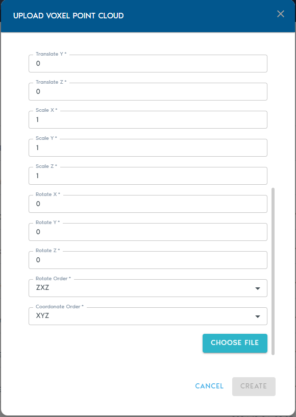](https://help.mystart.com/uploads/images/gallery/2025-03/VB3image.png) |
| **Field** | **Description** |
| **Item Name** | A clear, descriptive name for the new entity. |
| **Capture Device** | *(Optional)* A label identifying the capture device (e.g., “Riegl VZ-400i”, “Mobile LiDAR”). |
| **Capture Date** | *(Optional)* The original date of data collection. |
| **Horizontal Datum** | The horizontal reference system used in the point cloud data. |
| **Vertical Datum** | The vertical reference system for elevation values. |
| **Projection** | The spatial projection used for the dataset. |
| **Horizontal Units** | Units for horizontal coordinates (e.g., meters, feet). |
| **Vertical Units** | Units for vertical coordinates. |
| **Translate X/Y/Z** | Adjusts the position of the model along each axis. |
| **Scale X/Y/Z** | Rescales the model; a value of **1.0** retains the original size. |
| **Rotate X/Y/Z** | Applies rotation (in degrees) around each axis using Euler angles. |
| **Rotation Order** | Defines the sequence in which rotations are applied (e.g., XYZ, ZYX). |
| **Field** | **Description** |
| **Item Name** | A descriptive name for the new terrain entity. |
| **Source** | Select one or more **Point Cloud** or **Heightmap** entities to be used as the base for the terrain. |
| **Include** *(Point Cloud only)* | Choose which point classifications to include in the terrain model. By default, all points are used. |
| **Ortho-Imagery** | Select one or more **Ortho-Imagery** entities to be draped over the terrain. These can be aerial photos or computed textures. |
| **Detail Recovery – Use Point Cloud Colors** | If selected, the system will use RGB values from point clouds (if available) to generate an Ortho-Imagery set automatically. |
| **Detail Recovery – Generate Terrain Normals** | Requests the system to generate a high-frequency elevation detail set in the form of a **normal map**, enhancing terrain realism. |
| [](https://help.mystart.com/uploads/images/gallery/2025-03/uYVimage.png) | [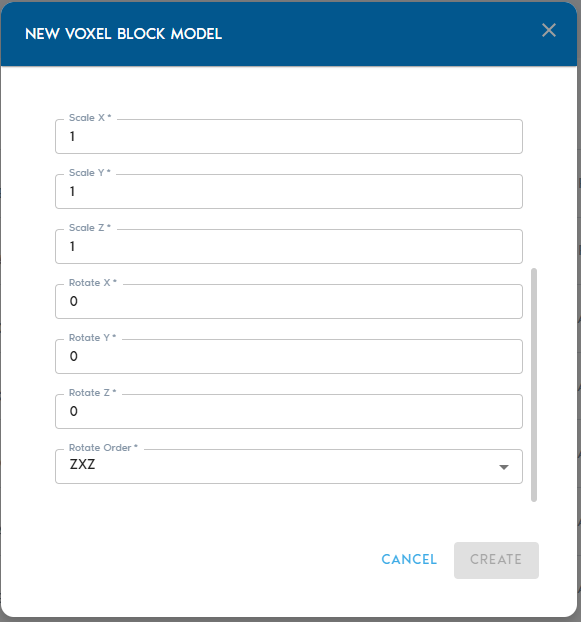](https://help.mystart.com/uploads/images/gallery/2025-03/WYMimage.png) |
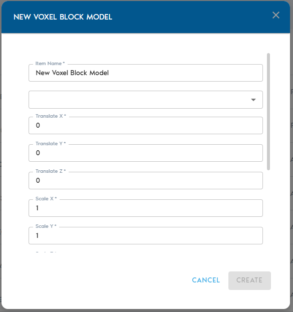
| **Field** | **Description** |
| **Item Name** | A readable, descriptive name for the new voxelized block model. |
| **Source** | Select a raw **Block Model** entity from the list. This will be used as the input for voxelization. |
| **Translate X / Y / Z** | Move the model along each axis by the specified value. |
| **Scale X / Y / Z** | Scale the model along each axis. A value of **1.0** maintains the original size. |
| **Rotate X / Y / Z** | Apply **Euler rotation angles** (in degrees) around the X, Y, and Z axes. |
| **Rotation Order** | Specify the sequence in which rotations are applied (e.g., XYZ, ZYX). |
| Name | A readable name for the new entity |
| Source | Shows a list of available Program entities. From this list, you can select which Program will be used by Voxel Generator. |
| **Field** | **Description** |
| **Program Name** | A readable, descriptive name for the program. |
| **Type** | Select the program type: **Voxel Generator**, **Report**, or **View**. |
| **Code** | Paste or write your custom Python code for the selected purpose. |
| **Field** | **Description** |
| **File Name** | A readable name for the export job. This will also be used as the exported file name when downloaded. |
| **Region** | Select the region of interest from the list of available project regions. This defines the spatial area for the export. > Refer to the **Working with Regions** section to learn how to define regions. |
| **Type** | Choose the data format for export: <ul><li>**Mesh** – Exports surface data as an .OBJ file</li><li>**Points** – Exports point cloud data as a .CSV file</li><li>**Raster** – Exports ortho-imagery as .TIFF with accompanying .TFW (world file)</li></ul> |
| **Resolution** | Choose the resolution level for the export. You may export at full (1:1) density or select a lower resolution depending on your use case. |
| **Source** | Select the dataset to be exported. This option is context-sensitive and will show compatible sources based on the selected export type. |
| Item Name | A readable name for the new entity |
| Minimum Height | Elevation value for black pixels in the heightmap |
| Maximum Height | Elevation value for white pixels in the heightmap |
| Capture Device | An optional string to identify capture device |
| Capture Date | An optional field containing the original capture date |
| Horizontal Datum | The horizontal datum used in the heightmap |
| Vertical Datum | The vertical datum used in the heightmap |
| Projection | The projection used by the heightmap |
| Horizontal Units | The horizontal unit type used in the heightmap |
| Vertical Units | The vertical unit type used in the heightmap |
| Image Format Extension | Expected World File Extension |
| .PNG (16bit grayscale) | .PGW |